I am keeping things simple, this is a no fluff page which hopefully you can view on old hardware too!
My challenge is to learn about the Dragon 32 I/O and interface to some electronics.
I am specifically looking at the Cartridge Port, but may also venture into the Printer and Joystick ports too!
Using a breakout cartridge PCB I have been attempting to get a simple chip select (CE) working.
I am currently trying to use a 74HC138 IC for this purpose.
I thought by using A15, A14, and /CTS (pins 39, 38, and 32) I could generate this CE.
I chose A15 and A14 as the Cartridge memory area should be mapped to $C000.
However so far this hasn't worked!
I cannot find many example circuits online for the Dragon Cartridge. However the couple I have found seem to be using A12 and A11 with /CTS (Pin 32).
This would imply that even though the A lines listed on the Edge connector go from A0 to A15 that they aren't actually the full 16-bit bus?
One Cartridge circuit I found has A11 connected directly to an EPROM /CE (meaning that A11 will be 0)
I need to work out the A12 logic as this goes through several gates but does seem to combine with /CTS.
So I'm still not sure how to determine if the Dragon is accessing the Memory on the Cartridge ($C000-$FFEF).
I did manage to get something working when I used Pin 36 (/P2) $FF40-$FF5F
This is labelled as PIA2 $FF40-$FF5F.
Using the HC138 I wired up like so:
| HC138 | Dragon Cartridge PIN |
| A0 | R /W |
| A1 | D0 |
| A2 | GND |
| /E1 | /P2 |
| /E2 | GND |
| /E3 | A15 |
I used D0 so I could poke a 0 or 1 to test I could pull a Data bit through.
Using the below BASIC code I observed pulses on the HC138 Y0 and Y1 pins (corresponding with D0)
10 A=65344
20 POKE A,1
30 POKE A,0
40 GOTO 10
So I still need to work out the logic for the main Cartridge memory area.
I would expect that pin 32 /CTS ($C000-$FFEF) would got low when access this memory area, but it doesn't seem to for me!
I went back to basics and decided to use my logic probe instead of the pocket oscilloscope.
Upon going down this route I found out that /CTS did do what I thought it did!
This means I am now moving forward again.
Next step I am going to wire up an old 2716 EPROM that I have here to see if I can read it.
I have wired up the 2716 EPROM and successfully dumped the contents.
Using this code (apologies for the quality of the images)
Here is some shots of it wired up plus the results of the dump.
I have no idea what this EPROM came out of!


I am now in the process of designing and breadboard testing my idea of using the /P2 $FF40-$FF5F addresses for both input and output.
I am currently going with a simplification of using address line A0 as the indicator of In or Out, ie. even addresses are output and odd are input.
I am leaving in place the ability to place ROM within the main Cartridge space so I could put some machine code routines in place if need be.
I have tested with a very crude single bit in and out so far.
Having not had much luck getting reliable bit shifting with a 5-bit shift register (74LS96) I decided to experiment to see if I could get an ATMEGA328 with some Arduino code to function as one.
It didn't need to be blisteringly fast to keep up with the dragon, and seems to work reasonably well.
So using the decoding mentioned previously (/P2 and A0) I am using Data bits D0, D1, and D3 from the Dragon's bus as a form of serial transmission.
D0 is the 'clock'
D1 is the Data bit
D2 is a command flag.
So by setting D1 as 0 I can clock in each bit. (it floats high when not active)
POKE 65344,0 <- clocks in a zero bit (0)
POKE 65344,2 <- clocks in a set bit (1)
POKE 65344,4 <- transfers byte to ATMEGA328 pins.
Then when D2 goes high the ATMEGA328 places the data on the pins.
Currently I only have 6 pins active, however the Arduino code is storing 8 bits.
Been a while since I have updated this!
I have had several steps backward trying to move beyond the breadboard.
Each prototype circuit has failed in some way.
This is where being able to produce circuit boards would be really useful.
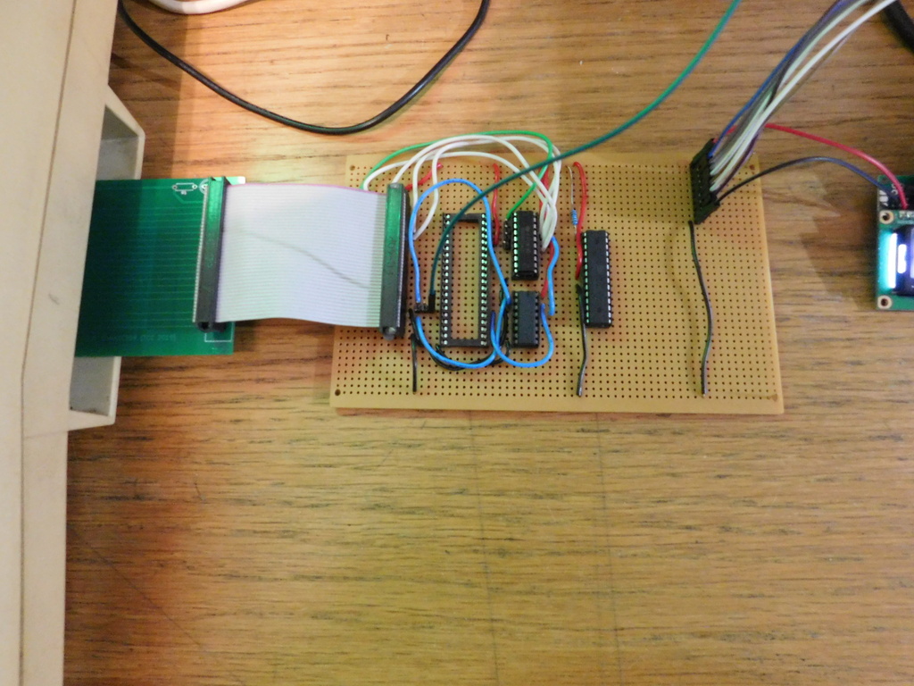
I do have the fundamentals of an 8-bit GPIO however I have yet to get it all on prototype board.
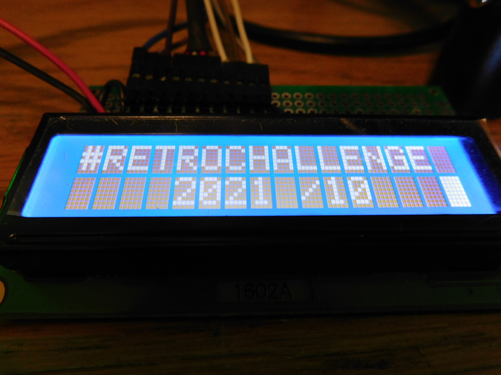
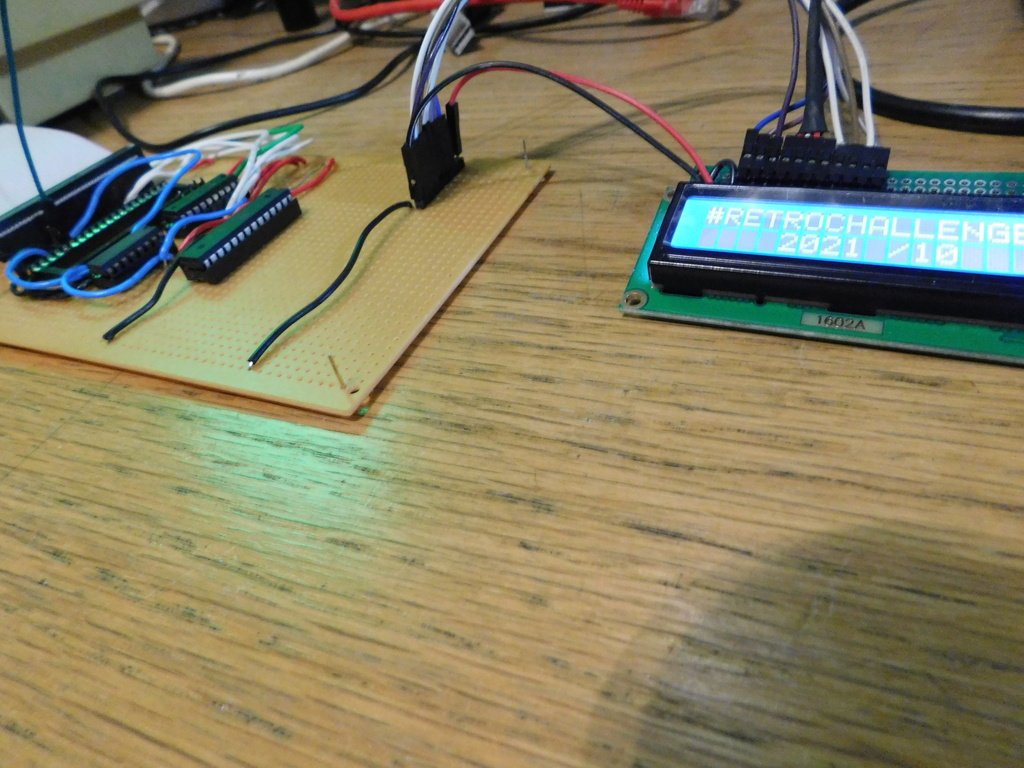
So yesterday I completed my RetroChallenge!
Using the 8-bit GPIO I manage to operate an LCD display via the GPIO using code written in Dragon BASIC.